Page 2 of 5
Re: K2 - Peak Compressor

Posted:
Mon Jan 23, 2017 12:14 amby RJHollins
we love it, whenever you do

Re: K2 - Peak Compressor
Posted:
Mon Jan 23, 2017 9:35 amby Spogg
I found experimentally, when messing around with my compressors, that there really is no one-size-fits-all.
Settings will depend on source material and what you want to achieve. This makes it tricky to produce meaningful presets for example.
Cheers
Spogg
Re: K2 - Peak Compressor
Posted:
Mon Jan 23, 2017 2:24 pmby Rocko
Hi,
Some examples would be nice, yeah...
Why not use elliptic filter for fast slopes and no latency?
Rocko
Re: K2 - Peak Compressor
Posted:
Wed Feb 08, 2017 11:34 amby Rocko
Hi,
Bumping up this topic again...
Why should one prefer to use FIR filters (with latency)? Is it due to phase issues on the Envelope Detector signals? Or is it the need for a steep slope?
Any comments are welcomed.
Rocko
Re: K2 - Peak Compressor
Posted:
Wed Feb 08, 2017 10:49 pmby martinvicanek
1. All filters have latency, IIR or FIR.
2. FIRs may be designed to have linear phase, resulting in the same latency for all frequencies.
3. IIRs have nonlinear phase, which means latency (or, more precisely, group delay) depends on frequency.
4. Moderately steep IIR filters step response will overshoot, steeper filters like elliptic will ring.
The ideal lowpass filter for level smoothing would have zero latency and perfect ripple suppression. Unfortunately that's impossible, so we have to compromise. A good filter is one with a small latency-bandwidth product.
The commonly used one-pole filter is not so good because it approaches steady state only slowly, and it does not do a good job in supressing ripples.
A higher order Butterworth filter has good ripple supression but it will overhoot a few times before reaching steady state. This may be perceived as pumping in a compressor. Moreover, if your input signal suddenly drops to zero, your filter output may actually drop below zero. Not good if you want to take log or power.
The reason why I favor a FIR for the envelope follower is that it can be designed to not ring, overshoot or creep. It follows the audio level with a finite delay. For linear phase, you get a natural indication for look-ahead time.
Re: K2 - Peak Compressor
Posted:
Wed Feb 08, 2017 11:31 pmby martinvicanek
Here is a pulsewith different envelope follower filters:
yellow: common single pole with different attack and release times.
green: 4-pole Butterworth filter
blue: FIR
- 1pole.png (41.15 KiB) Viewed 26881 times
- 4poleButterworth.png (39.58 KiB) Viewed 26881 times
- FIR.png (39.17 KiB) Viewed 26881 times
Re: K2 - Peak Compressor
Posted:
Sun Feb 12, 2017 9:55 amby Rocko
Thanks for the explanation. SUPER interesting.
This is all new to me, so I might be terribly wrong...
I'm testing this assumption here:
[Assumption]: For pro-audio compressors, the minimal release time could be something like 50 ms.
At such release times the ripples (of first order IIR at E.F.) have no effect.
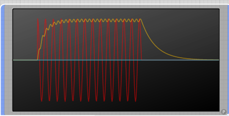
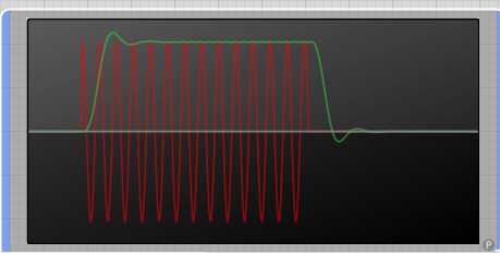
Images show a sine-wave signal which is amplitude modulted to have a 'burst' shape.
Signal shown with the 'gain signal'.
First image (gain signal in green) shows the ripples for a 100Hz signal with release = 50 ms.
Second image (gain signal in yellow) shows the ripples for a 100Hz signal with release = 5 ms. Much lower than the assumed minimum.
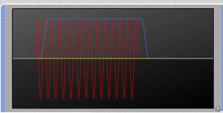
Third image (gain signal in red) shows the ripples for a 1000Hz signal with release = 5 ms.
From these images it seems to me that ripples are a none-issue (50ms release minimum).
Again, I'm quite new to this... Just asking.
Does this make sense to you ? Is this assumption good?
Can we say that 'first order IIR' can be used for Release greater than 50ms and signals 50Hz and higher?
Any comments are welcomed. Just learning here...
Re: K2 - Peak Compressor
Posted:
Sun Feb 12, 2017 10:53 amby nix
hey mate!
you have noise I the first and third plots,
also quick release is nice IMO
I agree, real interesting Rocko and Martin.
How does windowed RMS look I wonder.
Re: K2 - Peak Compressor
Posted:
Sun Feb 12, 2017 11:00 amby Rocko
you have noise I the first and third plots,
Sorry - please elaborate. Are you reffering to the images? Mine or Martin's? To me they all seem OK.
How does windowed RMS look I wonder.
I'll happily run some RMS tests and share the plots. But, let's first concentrate on the PEAK ones...
What do you mean by 'fast' release? Faster than 50ms?
My question is if we can assume that: "For fast release (shorter than 50ms) one can not rely on first-order IIR. For abover 50ms, it is good enough".
Thanks,
Rocko
Re: K2 - Peak Compressor
Posted:
Sun Feb 12, 2017 11:09 pmby nix
I was referring to your images Rocko,
the first and third ones start with some amplitude already.
Yep, faster than 50 ms.
My application is a hexaphonic electric guitar pitch to synth converter.
I use RMS atm. It requires a 10ms window at the moment.
So I need a follower of some kind to do the note on/offs.